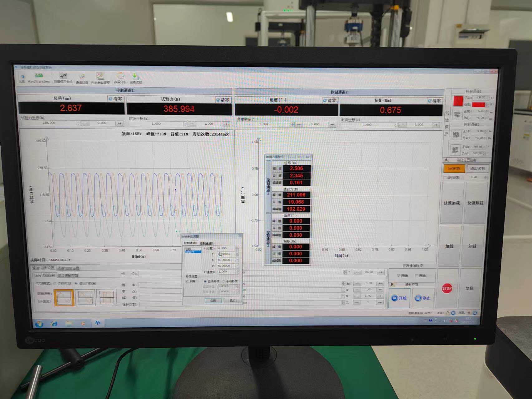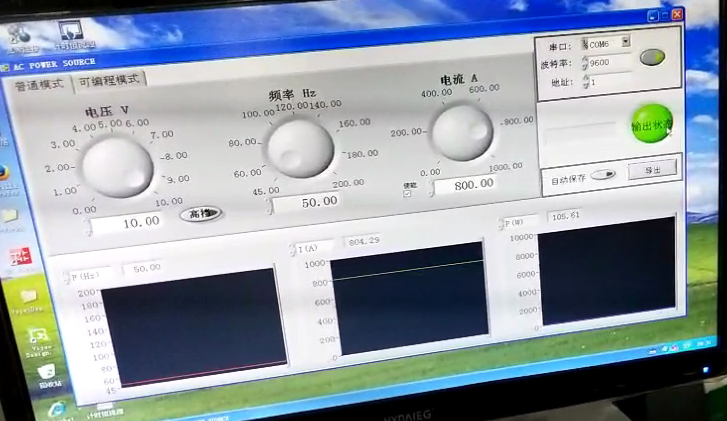
Testing machine host, electric control cabinet, full digital servo controller, multi-channel special control software and other key components are designed and manufactured by our company, power supply, touch screen module, contactor and other key purchased parts are selected international or domestic similar products in the famous brand, greatly improving the stability and reliability of the system.
1. Product introduction
PDS-1 multi-channel loading system (hereinafter referred to as testing machine) is one of the series of dynamic and static universal testing machine products developed by our company. During the development and development process of the testing machine, the company adopts the development and manufacturing experience of the internationally famous dynamic testing machine company, adopts the development concept of "unitization, modularization and standardization", absorbs the international advanced electromagnetic dynamic testing machine technology, and is designed according to the actual use situation of domestic users.
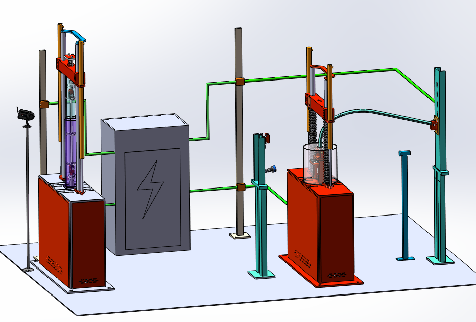
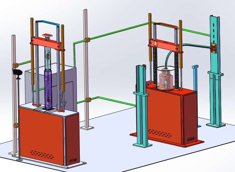
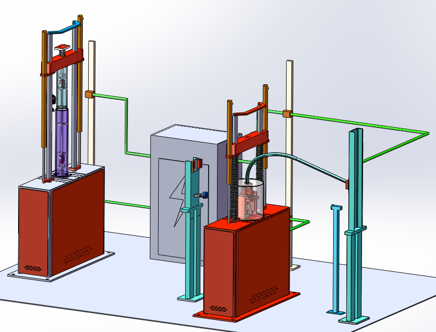
Testing machine host, electric control cabinet, full digital servo controller, multi-channel special control software and other key components are designed and manufactured by our company, power supply, touch screen module, contactor and other key purchased parts are selected international or domestic similar products in the famous brand, greatly improving the stability and reliability of the system.
1) System Overview
The PDS-1 multi-channel loading system is used for the fatigue test of the suspended string of high-speed railway. The testing machine is composed of a main machine (1KN electromagnetic linear actuator opposed above and below), test accessories, current source, insulation protection device, lateral load loading device, full power cabinet, full digital single-channel servo control system, computer printer, test software, and other necessary accessories.
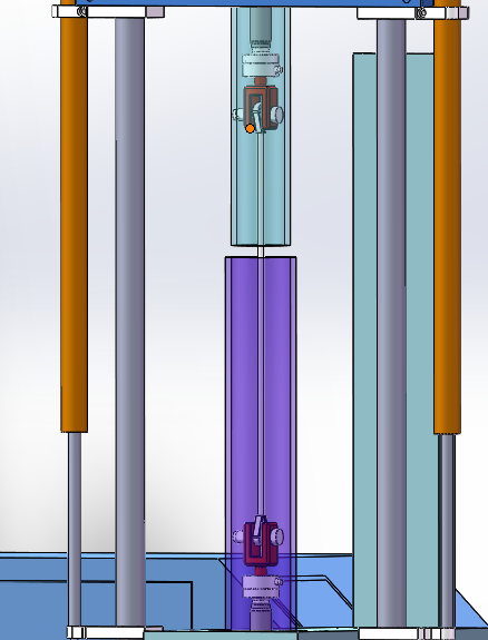
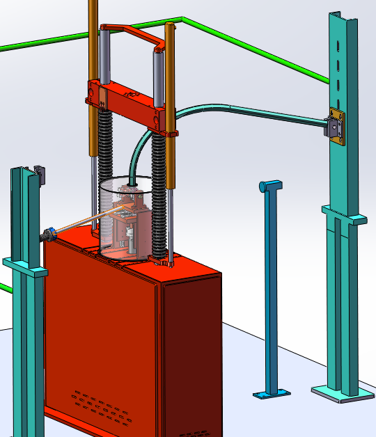

1.1 The working principle of the system is as follows:
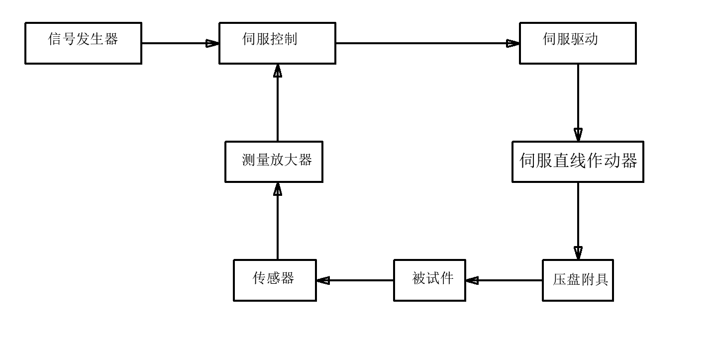
1.2 The system control block diagram is as follows
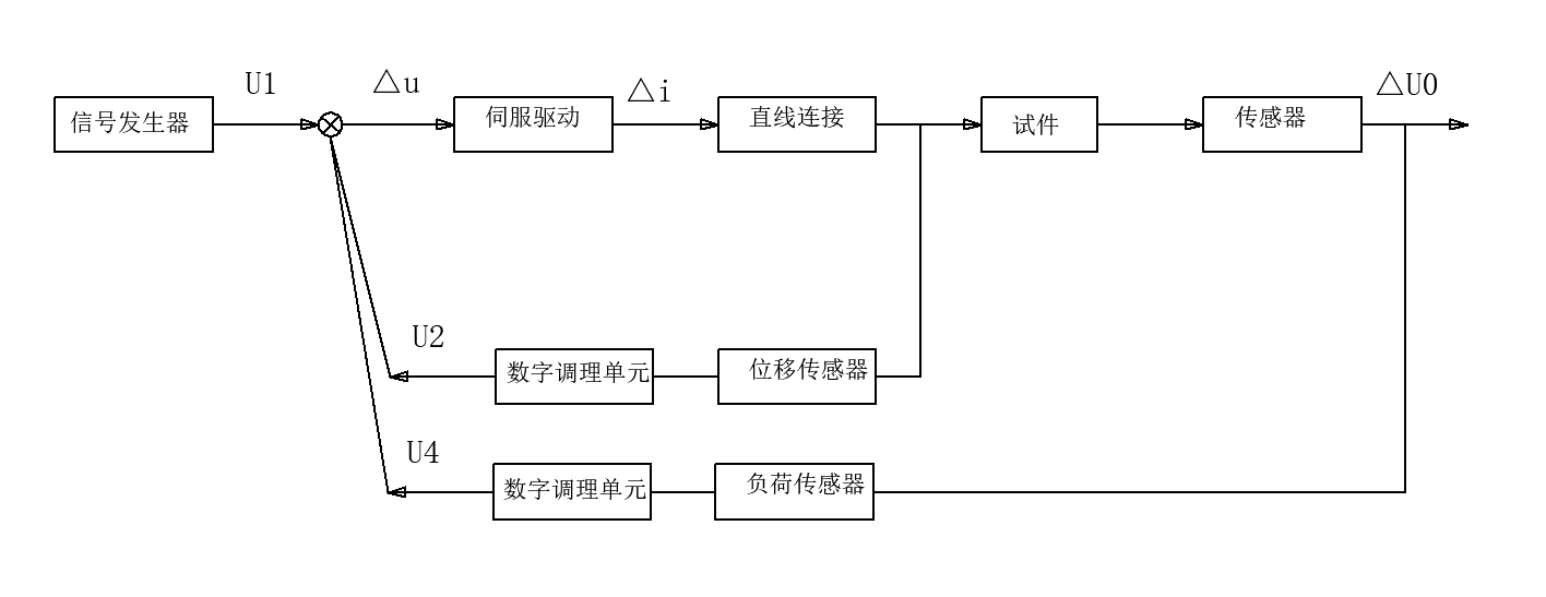
(Schematic diagram is for reference only)
1.3 System hosts Reference images are as follows
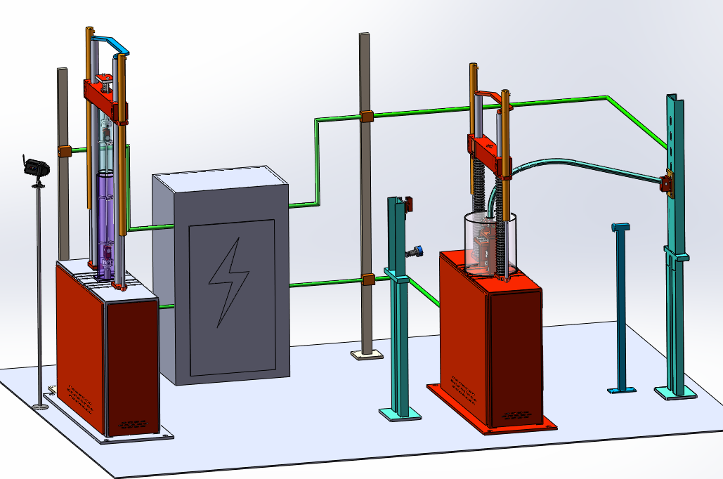
1.4 The main machine is a 2-column frame structure, and the 1KN electromagnetic linear actuator is installed on the main machine beam and the lower part of the workbench. The test fixture is respectively installed on the top of the two actuator piston rods. The host beam adjustment adopts electric lifting, mechanical clamping, elastic release structure, to ensure that the beam is stable and reliable during the test, and to ensure that the beam remains locked in the non-test state. The outer surface of the column is treated with hard chromium plating, which can effectively increase the anti-wear ability of the column, improve the anti-corrosion ability, and increase the beauty of the main body.
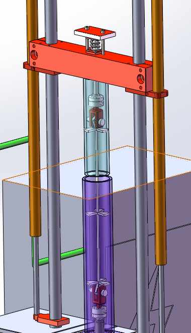
1.5 The movement of the beam (lifting and locking) is controlled by the beam drive module, two clamping devices and two lead screws are coordinated to complete the work, and the drive module adopts manual valve control, zero leakage, convenient and reliable.
1.6 The load sensor is installed on the end face of the piston rod for measuring the test load. The isolation layer is reserved at the connection.
(Note: 1 suspension sensor is installed on the upper part of the main engine, and 2 wire clips are installed on the end of the piston rod)
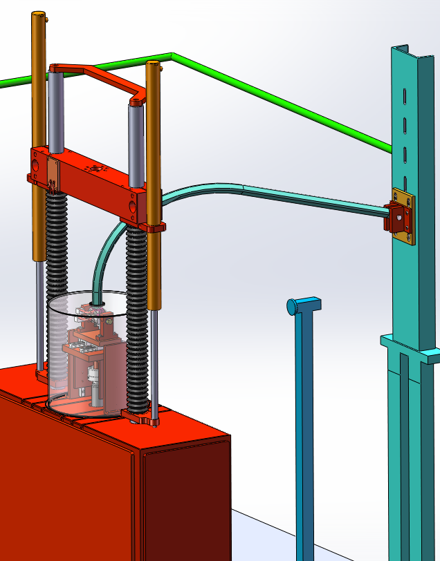
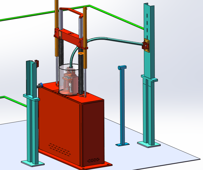
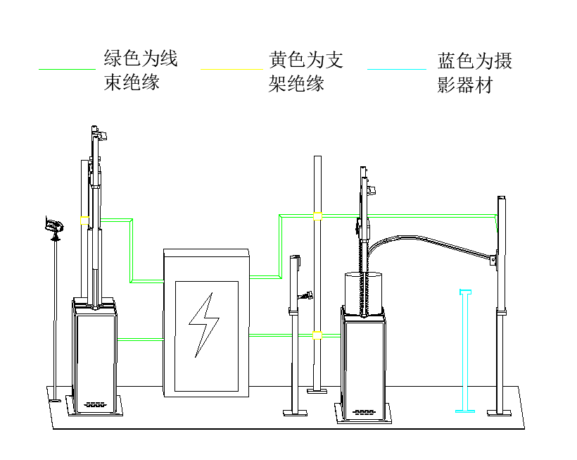
1.7 In order to prevent the conductor from falling off or vibrating loose during the test, the whole machine is equipped with a wire conversion bracket to prevent the above situation. During on-site installation, the power module connects the main wire to the wiring bracket near the equipment through a standard bridge, and the bracket and the sample are connected by a certain length of wire (high flexible wire).
As shown in the figure
1.8 Reliability and Safety:
1) Solid insulation: Keep the test string powered up during vibration without falling off. Use insulation film to cover the exposed metal of the upper beam components, workbench components and lower end platform (red in the picture is the film). Use circular shield to protect the columns on both sides without affecting the lifting of the beam. The wiring harness should be fixed, and insulation materials should be used in many places to take insulation protection measures with other equipment parts;
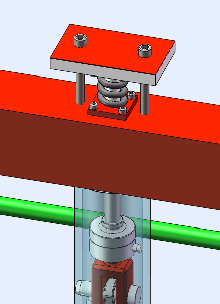
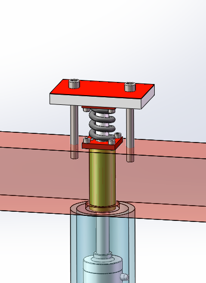
2) The pull rod is fixed on the beam with bolts, and the insulation sleeve is used between the pull rod and the beam, and the spring device is placed in the middle. When the testing machine is working, the pretension force needs to be applied to the spring, and the size of the pretension force is controlled by the fixed bolt (red is the insulation material covered);
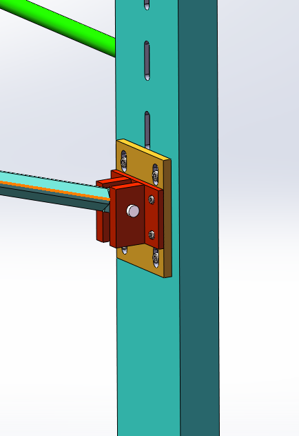
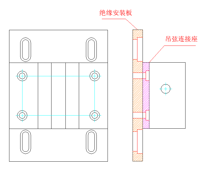
3) The hanging string connecting seat (covered with insulation film) is connected with an insulation mounting plate, and the waist hole of the insulation mounting plate can adjust the height of the hanging bow connecting seat;
4) Conductivity: the rated current should meet the output current of the current generator, without a large amount of current loss and interference with the current waveform;
5) The connecting wire of the current generating device should be resistant to corrosion, oxidation and external insulation;
6) The joint part of the fatigue testing machine and the current generating device requires high mechanical strength and easy installation;
7) Can adapt to the inspection string length range (contact line surface to the lower surface of the cable) : 800~1600mm;
8) Actuator, slide table, upper and lower beam, reserve multiple holes to facilitate the test requirements of different working conditions. (The sensor and corresponding fixture can be interchangeable)
9) Insulation material protection device is placed between the wire clamp tooling and the bracket.
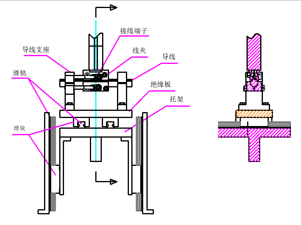
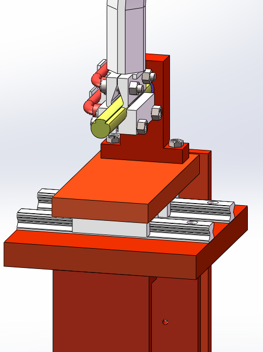
Note: 1. When the bracket moves up and down, the two side slide blocks move up and down along the vertical slide rail, and the two side slide rails will not affect other parts.
2. When working, the sliding block under the insulation board can move on the sliding rail above the support plate
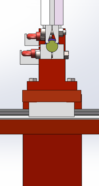
10) The wire is double clamped by the upper and lower two wire clamps, the wire and the support are insulated with ceramic rings, and the metal parts are covered with insulation film (red in the figure is the insulation film).
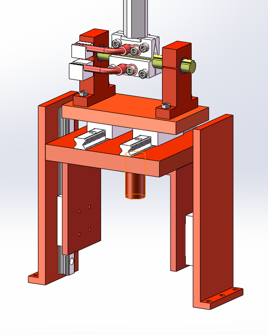
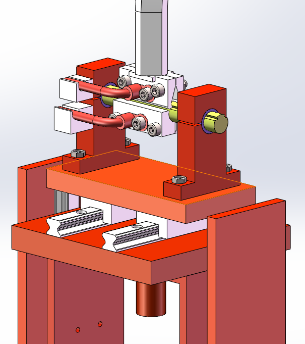
11) The wire clamp is locked by bolts, the clamp connection is insulated, and the wire harness is bound to the fixed position of the wire clamp.
2. Actuator:
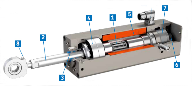
2.1 The electromagnetic linear actuator is the core component of the testing machine and outputs power through the actuator. Designed and manufactured with its own technology, it is composed of actuator body, electromagnetic control module and sensor.
Basic parameter
The actuating cylinder is placed under the table.
Maximum dynamic force: ±1150N.
Maximum static force: ±1150N
Actuator effective stroke: +/-100mm(total stroke 220mm);
Maximum compression stroke 110mm at 2hz
When the maximum compression stroke is 20mm, the maximum frequency is 11hz,
The duration of the experiment is not less than 500w times.
Actuator comes with SONY high precision laser displacement sensor,
The actuator amplitude limit position is designed as buffer to avoid running out of control and causing damage;
The system adopts the anti-backlash device, the force value is automatically centered, the side force is reduced, the impact of the high frequency tension test is reduced, and the test waveform is improved.
2.2 Special clearance elimination devices are designed at the joint screw between the load sensor and the chuck and the piston rod and the chuck to further improve the dynamic response performance.
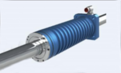
3. Test accessories
Special ceramic fixture is used for fatigue test of hanging string.
The key parts such as the pressure disc are treated with special technology, which has the characteristics of high hardness and good wear resistance (no insulation).
The positioning protection device ensures the safety of the hanging string during the fatigue test, ensures that the hanging string breaks during the test, and the broken end does not jump, prevents the broken end from contacting any position of the equipment, and prevents electric shock.
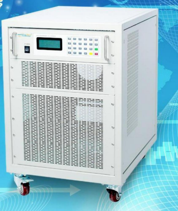
4. Current generating device
1) Power supply: AC 220V/AC 380V 50Hz;
2) Output current 0~1050A AC (standard sine wave) /DC, the lowest output current reaches 300A, current accuracy error ≤±0.5%;
3) Output voltage 0-10VDC, accuracy error ≤±0.5%;
4) The output current waveform is adjustable, the loading frequency is adjustable, and the true RMS value of the current is continuously adjustable;
5) The device should ensure that it can continue to work in the test process, with independent control of power on, power off time, control time minimum resolution of 1ms;
6) With real-time waveform display, power on time setting, power off time setting, and can be independent power off at the end of the test (sample fracture) or have other protective insulation measures;
7) Current waveform distortion design should meet the corresponding national standards and industry standards;
8) The output AC frequency should be in line with the actual field, 50Hz;
9) The device should have the function of overcurrent and overvoltage;
10) Can measure the current action time of the hanging string, and can synchronously record the locking action time;
Software part:
11) Dynamic current curve, average current (RMS) curve display function, maximum and minimum peak current real-time value display, historical current peak record.
Detailed parameters:
| Production method | SPWM | |
| INPUT | Phases | 3φ4W |
| Voltage | 380V±10% | |
| Frequency | 47HZ-63HZ | |
| OUTPUT | Phases | 1φ2W |
| Voltage Constant current source | 10V(Opening voltage) | |
| Current Indicates The Constant Current Source | 0~1000A Adjustable | |
| Frequency | 45HZ~200HZ | |
| Wiring | Copper strip extraction | |
| Protection | Electronic circuit quickly identifies over current, over voltage, over temperature automatically off, non-test state VA=0 | |
| LED Display | Voltage Vms, current Arms, frequency Fre, power Wattage, power factor PF | |
| Power adjustment ratio | 0.1% | |
| Load adjustment rate | 0.5%FS | |
| Waveform distortion rate | 3%(pure resistive load) | |
| Frequency Regulation | 0.01% | |
| Voltage resolution | 0.1V | |
| Current resolution | 0.1(A) | |
| Frequency Resoulution | 0.1HZ | |
| Measurement Accuracy | Voltage | 0.5%FS+5dgt |
| Current | 0.5%FS+5dgt | |
| Wattage | 0.5%FS+5dgt | |
| Frequency | 0.01%FS+5dgt | |
| Set accuracy | Current | 0.5%FS |
| Frequency | 0.3%FS | |
| Protection | Over Current; Over Temp; Over Load | |
| Environment | Temperature:0℃-45℃; Relative humidity:0-90%(non-condensing state); Altitude:1500m | |
| Insulation reactance | 500Vdc 20MQ or higher | |
| Voltage insulation | 1800Vac/5mA/1min | |
| Cooling mode | Forced fan cooling | |
| W*H*D(mm) | W:550 H:700 without castor D700 | |
| Efficiengy | ≥98% | |
| Noise | ≤60DB(1m) | |
| Protection level | IPX20 | |
5. Control system:
5.1 Number of control channels: 2, including three closed-loop control loops of test force, test displacement and test deformation, with control mode undisturbed smooth switching function. The maximum closed-loop control data refresh frequency is 1kHz; The resolution of controller A/D and D/A is 16 bits. Signal frequency range: 0.001Hz ~ 100Hz; Signal generator waveform: sine wave, triangular wave, square wave, sawtooth wave, etc. The servo drive unit is used to drive the linear motor; Remote servo enable control function for remote control linear motor drive power; The controller has the function of limit parameter setting and complete protection function. In addition to overload (110%) protection and secondary overcurrent protection, it also has arbitrary dynamic load protection, static load protection, frequency protection and so on.
5.2 Dynamic testing machine (system) control software: System management software: The software is the basis of the whole digital servo controller, its main functions are to manage the hardware resources of the control system, define the sensor, adjust the digital control parameters, set the protection, display the current control mode, and function generator status and sensor calibration. The dual trace digital oscilloscope, digital servo ammeter and 6 digital voltmeters are provided for real-time display of test data. Function generator software: The software is mainly used for constant amplitude dynamic test, such as constant amplitude fatigue test. The function generator software will automatically track and correct the peak and valley values of the control quantity (such as load) to ensure that the typical dynamic error value of each peak is ±0.5%FS during the whole test process. During the test, the operator can dynamically change the peak, valley and frequency, and can also perform manual or automatic signal holding. If the automatic signal holding cycle interval is set, Each time the number of test cycles is increased by one cycle interval, the software will automatically maintain the signal at a set level to facilitate the measurement of some test data (such as visual crack length). The optional waveforms of the software are sine wave, triangle wave, square wave, oblique wave, sawtooth wave, combined wave, combined oblique wave test. At the end of the test, the software will save some important data, such as test load, frequency, number of cycles and test time. The software can also perform simple static tests. Multifunctional test software: The software is a flexible, fully functional test software, users can use it to design special test methods, but do not need programming. This software has a variety of control functions, data acquisition functions and other auxiliary functions of the servo controller are done on a panel in the form of ICONS, users can drag and drop these function ICONS into the test definition panel with the mouse, and combine them according to user needs at will, you can test according to user-defined test methods.
Function generator software: The software is mainly used for constant amplitude dynamic test, such as constant amplitude fatigue test, constant amplitude fatigue crack growth test, etc. The function generator software will automatically track and correct the peak and valley values of the control quantity (such as load) to ensure that the typical dynamic error value of each peak is ±0.5%FS during the whole test process. During the test, the operator can dynamically change the peak, valley and frequency, and can also perform manual or automatic signal holding. If the automatic signal holding cycle interval is set, Each time the number of test cycles is increased by one cycle interval, the software will automatically maintain the signal at a set level to facilitate the measurement of some test data (such as visual crack length). The software optional waveforms are sine wave, triangle wave and square wave. After the test, the software will save some important data, such as test load, frequency, number of cycles and test time. The software can also perform simple static tests.
Multifunctional test software: The software is a flexible, fully functional test software, users can use it to design special test methods, but do not need programming. This software has a variety of control functions, data acquisition functions and other auxiliary functions of the servo controller are done on a panel in the form of ICONS, users can drag and drop these function ICONS into the test definition panel with the mouse, and combine them according to user needs at will, you can test according to user-defined test methods.
5.3. Controller technical parameters:
5.3.1 All-digital universal signal conditioning unit: test force, displacement closed-loop control loop.
5.3.2 The maximum closed-loop control data refresh frequency is 10kHz.
5.3.3 Controller A/D resolution is 18 bits and D/A resolution is 16 bits.
5.3.4 Signal frequency range: 0.01Hz ~ 100Hz.
5.3.5 Signal generator waveform: sine wave, triangle wave, square wave, program wave.
5.3.6 Can realize half-period displacement control half-period force control, or customer custom waveform to complete other tests of the specimen
5.3.7 Control accuracy: the static control accuracy is 0.3% FS, and the typical dynamic control accuracy is 0.5% FS.
5.3.8 Remote servo start and stop control function.
5.3.9 Counter capacity: Unlimited times.
5.3.10 Other necessary I/O input and output units: four analog inputs, four analog output interfaces; Four digital input and four digital output interfaces (optional).
6. Other configurations and necessary accessories:
Reaction frame for calibrating load sensor;
Configure compression accessories;
With safety shields,
Matching fixture and tooling for suspension and wire clamp test
7. Main technical performance indicators:
1. Maximum static test force: ±1150N, static display accuracy:, display accuracy from 5% per file ±0.5%;
2. Maximum dynamic test force: ±1150N; Dynamic volatility: not more than ±0.5%FS.
3. Maximum amplitude of the actuator: ±100mm, indicating accuracy: ±0.5%FS.
4. Operation range: 0-20Hz.
5. Control mode: load control, displacement control;
6. Main test waveform: sine wave, square wave, triangular wave, oblique wave and external input waveform;
7. Single machine power :11kw
8. Power of a single current source: 10kw
9. Overall dimensions 750*700*2700 and 750*700*2250
