
If sounds no voice(motor starting) after turn on the power,please turn off the power inmmediately,and check the motor and the wire!
Warnings:
1. If sounds no voice(motor starting) after turn on the power,please turn off the power inmmediately,and check the motor and the wire!
2. Do not removal or repair the machine during the machine working or internal pressure in machine!
3. Do not overload testing!
4. Tank and oil line keep away from dust!
Overview:
The electric rock stress direct shear instrument is developed according to the provisions of the national industry standard (SL264-2001) "Rock Test Regulations for Water conservancy and hydropower Engineering", (JTG E41-2005) "Highway Engineering Rock Test Regulations".
The instrument adopts the flat pushing method, which is mainly suitable for the direct shear test of rock block, structural plane (such as joint plane, in-layer, in-slice, crack surface, etc.) and the contact surface (bonding surface) between concrete (or mortar) and rock, as well as the shear strength test of the joint surface between concrete and other materials. Its structural properties fully meet the requirements of the test specification.
Constitution
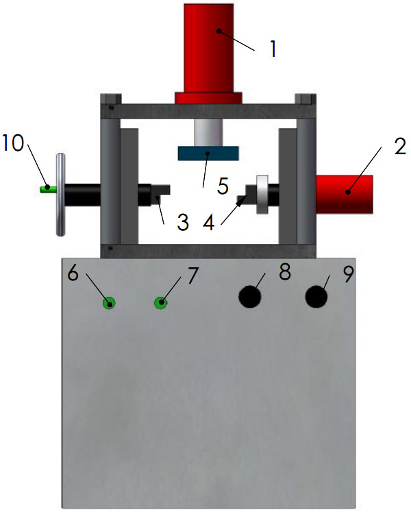
1.Normal Load hydro-cylinder;
2.Lateral load hydro-cylinder;
3.Left shear equipment:
Controlled by 10th part(Hand-wheel); Move left or right;
4.Right shear equipment:
Controlled by 9th part (Valve of Lateral load); Move fast or slowly;
Controlled by 7th part(Switch of Lateral load); Move left or right;
5.Pressure plate:
Controlled by 8th part(Valve of Normal load); Move fast or slowly;
Controlled by 6th part (Switch of Normal load); Move up or down;
6.Switch of Normal load:
Turn left , the 5th part move up;Turn right ,the 5th part move down ;
7.Switch of Lateral load:
Turn left , the 4th part move left(Forward); Turn right ,the 4th part move right(Back);
8.Valve of Normal load:
Turn clockwise, the 5th part move slowly; Turn anticlockwise,the 5th part move fast ;
9.Valve of Lateral load:
Turn clockwise, the 4th part move slowly; Turn anticlockwise,the 4th part move fast ;
10. Hand-wheel:
Rotate it , the 3rd part move left or right;
Details
|
1.Switch of Normal load Normal load Up stop down |
3.Valve of Normal load Normal load On ←→ Off |
 |
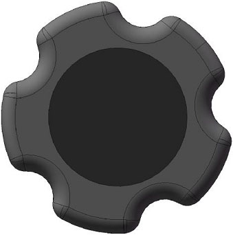 |
|
2.Switch of Lateral load Lateral load Forward stop back |
4.Valve of Lateral load Lateral load On ←→ Off |
 |
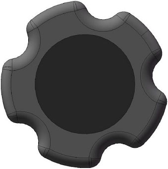 |
Main technical parameters:
Normal load: 0~500kN
Normal overload protection: over full load 2%
Normal working stroke S: 0~100mm
Lateral load: 0~300kN
Lateral overload protection: over full load 2%
Horizontal working stroke S: 0~150mm
Normal space: ≤450mm
Horizontal space: ≤200mm
Shear load speed: 0~30KN/S (adjustable)
Load indication mode: microcomputer screen display
Load indication accuracy: 0.1KN
Displacement measurement: microcomputer acquisition
Loading mode:
Normal: microcomputer control electro-hydraulic servo valve (can also be manually);
Transverse: manual hydraulic valve;
Lenovo PC (CL E3400 1G DDR2 160G DVD 19 "LCD)
HP inkjet printer
Motor power: 1kW+1kW
Working voltage: three-phase four-wire system 380V 50Hz(three-fire zero)
Weight: 2200kg
Dimensions: 1500×900×1735mm
Equipment working conditions
1.Power supply: Three phase and Four wire
three live wire, one zero line
2.Wiring definition: Brown - live wire, Yellow - live wire, Blue - live wire, Black – zero line
3.Main motor power: 2.2kW Total;
4.Max . Normal load: 500kN;
5.Max. Lateral load: 300kN;
6.hydraulic oil: 46# Hydraulic Oil@cold area or season; 68# Hydraulic Oil@hot area or season;
oil bearing: 40L;
7.Weight of machine: about 2000kg;
8. In a vibration-free environment.
9. The power supply voltage fluctuation range is less than ±10% of the rated voltage.
10. The foundation should be smooth and firm.
Test Run:
1. Refueling: The oil adopts 46# anti-wear hydraulic oil, the refueling hole is in the left rear of the instrument, open the left rear cover plate, open the protective cover of the refueling port above the oil tank, and refueling can be done, the oil amount is about 40L.
2. Power connection: Please firmly connect the three-phase power supply, do not lose phase.
3. Test run:
After closing the air switch, the oil pump starts immediately, and there is hydraulic oil flow in the system immediately; If the situation is normal, the working piston can operate as indicated by the manual reversing valve:
1. The normal switch has three positions, in which the "up" piston goes up, the "stop" piston stops, and the "down" piston goes down.
There are three positions of the lateral switch, in which the "left" piston walks to the left, the "stop" piston stops, and the "right" piston returns to the cylinder.
If the motor is running and the piston is not moving, the motor may be reversed, and the phase sequence of the power supply can be adjusted.
(Note: Each reversing valve is equipped with a speed control "oil feed valve", be sure to open, otherwise the piston will still not move)
Use method and operation sequence (manual) (can be omitted for electro-hydraulic servo models)
1. Ensure that the normal and horizontal "oil supply valves" are tightened (closed) and the two switching switches are in the "stop" position.
2. Open the "air switch" (three-phase switch), the oil pump starts to supply oil, turn on the power supply of the digital display meter, and connect the sensor connection line.
3. Place the test block installed with the "test mold box" on the "roller row" (low friction system) so that it is centered (right below the normal piston live "force transfer pad").
Note: 1) The gap between the specimen and the inner wall of the shear box is filled with filler, so that the specimen and the shear box become a whole. The predetermined shear plane should be located in the middle of the shear joint.
2) The direction of action of normal load and shear load should pass through the geometric center of the predetermined shear plane.
4. The normal displacement meter and horizontal displacement meter are firmly placed, and the fulcrum of the measuring rod must be set outside the influence range of shear deformation.
5. Adjust the "normal switching switch" to the "down" position, slowly release the "normal oil supply valve", so that the normal force gradually increases, the pressure value can be read directly on the computer, fine tune the oil supply valve to maintain its pressure, read and record the displacement value.
(The oil supply valve can be properly fine-tuned to ensure normal force stability)
Note:
According to the standard:
1) The maximum force of the method should be 1.2 times of the engineering pressure. For the specimens with weak fill in the structural plane, the maximum normal load should be limited to not extruding the fill. Normal load should be graded according to the number of grades, the number of grades should not be less than 5, each level of 3 specimens.
2) For specimens that do not need consolidation, the normal load can be applied once and the normal displacement can be measured immediately.
Specific provisions to do the test, according to the standard.
6. Adjust the transverse handwheel to tighten the shear surface of one end of the specimen.
7. Adjust the "transverse force switch" to the "left" position, slowly release the oil supply valve, so that the shear force rises at a certain speed (0.4MPa/min). (The specific speed is manually adjusted according to the standard)
Note:
Apply shear load:
1) The estimated maximum shear load is divided into 10~12 stages. After each stage of load is applied, the shear displacement and normal displacement are measured immediately, and the next stage of shear load can be applied again after 5 minutes. When the shear displacement is significantly increased, the stage difference can be appropriately reduced. The shear load applied before the peak should not be less than 10 levels.
2) After the specimen is cut, the shear displacement table is adjusted, and the friction test is carried out according to the above regulations under the same normal stress. If necessary, the normal stress can be changed to carry out a single point friction test.
8. Description of the shear surface after the test:
A. Accurately measure the shear surface area.
B. The damage of the shear surface, the distribution, direction and length of the scratches are described in detail.
C. The fluctuation difference of the shear surface is measured and the curve of the section height along the shear direction is drawn.
D. When there is filler in the structural plane, the position of the shear plane should be accurately judged, and its composition, properties, thickness and structure should be described. Determine the physical properties of the fill as required.
In this test, at least more than 3 specimens were used for parallel measurement.
Maintenance, maintenance, accident removal
1. The instrument should be used indoors.
2. Wipe moving parts frequently to keep them moving freely.
3. Repair and tighten fastening parts when they are loose.
4. The oil should be replaced with the same type of oil after one year of use.
5. After the test is completed, the reversing valve should be reversed to the "stop" position as soon as possible, so that the oil pump is running under no load.
6. In use, there is no pressure indication on the pressure gauge or digital display meter or the cylinder is not working:
1) The pressure gauge is damaged due to collision or the digital display meter is not connected to the sensor cable.
2) No oil pump:
a. Winter oil viscosity is large, summer oil viscosity is small.
b. The oil spill bolt under the oil pump is not tightened.
c. The phase of the three-phase voltage is wrong, and the two items can be exchanged arbitrarily.
Seven. Leakage: Long-term use will occur in the tubing joint leakage, there may be "O" ring aging, composite ring aging, replacement is appropriate.
How to test
1.Turn on the power: the machine’s and the PC’s;
2.Run the software;
3.Set the Param that you want to test, just as:
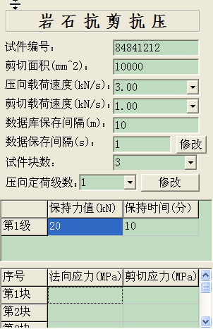
4.Place the specimens among the pressure plate underneath; Make sure that the Valve of Lateral load was turn off!
5.Turn the Normal load Switch right, and turn on the Normal load Valve(Turn anticlockwise a little),then the Pressure plate move down; When the Pressure plate get in touch with the specimens, turn off the Normal load Valve; Click the Start button , then the PC will control the servo valve to load the pressure that preset in step 3 above; The Switch of Normal load was turned right! Make sure that the Valve of Lateral load was turn off!
6.When the VForce(VForce = Normal Load) area displayed the pressure that preset in step 3 above: And when the VForce doesn’t change to much, Rotate the Hand-wheel,to make 3rd part above move right, until the 3rd part get in touch with the specimens. The Switch of Normal load was turned right! Make sure that the Valve of Lateral load was turn off!
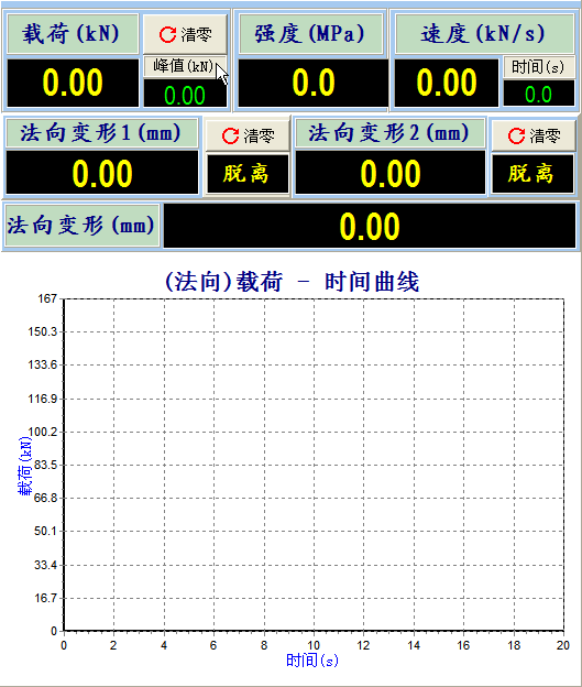
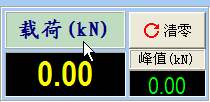
7. Click the button to clear the VDefor that displayed; The Switch of Normal load was turned right! Make sure that the Valve of Lateral load was turn off!

8. Place the dial indicator perpendicular to the left side of the specimens, click the button to clear the HDefor that displayed;

9. Click the button to get ready to record the data; The Switch of Normal load was turned right!
10. Turn the Switch of Lateral load left, and turn on the Valve of Lateral load,then the Right shear equipment move left ,when it get in touch with the specimens,move the Right shear equipment slowly;
11. When the specimens was broken or the test was finished,click the button to stop; Save data.
12. Click the button to stop Lateral load, and the Lateral load will stop.
13. Turn the Switch of Lateral load right to make the Right shear equipment move right,and remember to turn the Switch of Lateral load at middle position after the Right shear equipment stop move;
14. When the VForce displayed closed to zero, turn the Switch of Normal load left,and turn on the Valve of Normal load to make the Pressure plate move up; When the Pressure plate stoped, turn off all the switches and the valves!
 Fully Automatic Multi-Field Coupling Soil Triaxial Instrument
 Electric Percussion Testing Machine For Coarse Soil
 Coarse-Grained Soil Horizontal Permeability Test Machine
 Coarse-Grained Soil Vertical Permeability Deformation Tester
 Coarse-Grained Soil Direct Shear And Compression Testing Machine (Integrated Machine)
 Frameless Frame Type Low Stress Triaxial Testing Machine