
This series of testing machine is mainly composed of the main machine (frame structure), fixed beam, moving beam, loading system and related test software components, etc. The test space is in the lower part of the main machine, which is convenient for the installation of the sample and the corresponding auxiliary equipment. This series of testing machine is mainly used for static tensile mechanical properties test of cables, steel cables, ropes, chains and mining three-ring chain four-ring chain and parts, widely used in metal products, building structures, ships, military and other fields. According to the different control methods can be fractional explicit, microcomputer screen explicit, microcomputer control electro-hydraulic servo, etc., travel space and maximum test force according to user needs special design.
1. Device description
1) The testing machine is mainly applicable to the tensile test of all kinds of steel wire rope, anchor chain, rigging, shackle and other specimens.
2) Frame structure host, single rod double acting cylinder.
3) High-precision tension load sensor to measure force, photoelectric encoder to measure displacement.
4) Semi-open stretch attachment (can also be designed separately other clamping attachment) convenient and reliable. Accessories can be selected according to different types and different specifications of samples.
5) The moving beam can facilitate the adjustment of the test space, and it is equipped with the pin cylinder and the pump station to realize the automatic pin pulling.
6) The use of electro-hydraulic servo control technology, with test force, displacement and other closed loop control loop, can be loaded in stages. The microcomputer automatically collects the data and processes the data.
2. Appearance diagram
The appearance is shown in Figure 1
3. Main contents and scope of application
The testing machine adopts the frame structure of the frame, the single rod double action piston cylinder to apply the test force, the load sensor to measure the force, the stretching space can be adjusted according to the length of the sample specification, the loading mode of the test force can be controlled by the computer, and the test data can be automatically processed according to the requirements of the test method. The machine does the product tensile test for the mining industry, which is used for steel wire rope, anchor chain, lifting belt. The tensile load, damage and other tests of products such as safety belts require flexible and convenient operation, slow and stable loading, and strong carrying capacity of the body. The key parts of the oil source - oil pump electric unit, relief valve, reversing valve are brand-name products, self-developed full digital amplifier, used to achieve three closed-loop control of the system.
4. Main technical parameters and specifications
1. Maximum test force: 3000kN;
2. Measuring force range: 12 ~ 3000kN;
3. Test force accuracy: ±1%;
4. Test space: 1000mm;
5. Piston stroke: 1000mm;
6. Displacement measuring range: 1500mm
7. Displacement measurement resolution: 0.01mm;
8. Pull head no-load fast forward speed: not less than 150mm/min;
9. Test speed: 0-100mm/min;
11. Force measurement method: load sensor force measurement;
12. Control test mode: the computer automatically controls the test process, the computer screen displays the test force and test curve, and automatically processes the test data according to the requirements of the test method;
13. The overall size of the host is about (length * width * height) : 1000x1200x2900
14. Can display a variety of test curves: force-displacement, force-time, force-deformation, stress-strain, etc.
15 The console is separated from the host, with a safe distance, and the host should have security protection measures
16. Special protective device to prevent injury when the chain is broken
5. Working conditions
a) Ambient temperature: 10 ~ 35℃;
b) Relative humidity is not more than 80%;
c) No vibration in the environment;
d) No corrosive media around;
e) Horizontal installation on a stable basis; Levelness not greater than 0.2/1000;
f) The fluctuation range of the power supply voltage shall not exceed ±10% of the rated voltage.
6. Structure characteristics and working principle
The machine is composed of main engine, electric control cabinet, oil source and so on.
6.1 Host Parts
When the independent oil source controls the oil into the cylinder, the piston moves forward, and the moving cross beam is driven by the workbench, and the clamp seat is moved, so that the specimen can be stretched in the stretching area.
The cylinder and piston are important parts of the main engine, their contact surface is precision machined, and maintain a certain fit clearance and oil film, so that the piston can move freely and reduce friction to a minimum.
A piston displacement detection device is arranged between the base and the workbench, and the fixing frame is connected to the base with screws, on which a scale scale and an upper limit of the oil cylinder are installed.
6.2 Oil source and hydraulic principle
The oil source is composed of oil tank, oil pump electric unit, high pressure oil filter, oil return valve, superimposed relief valve, electromagnetic reversing valve, proportional valve, etc.
Hydraulic principle of oil source (see Figure 3) :
The hydraulic oil output of the oil pump motor unit enters the valve block through the high pressure oil filter, and the flow rate of the proportional valve can be controlled by the computer to realize the piston forward, backward and loading speed, and realize the load maintenance. Fast forward and fast rewind can realize the rapid movement of the cylinder (do not use this function when doing experiments) (as shown in the picture)
7. Measurement and control part
SmartTest controller and data acquisition and processing system
(Controller with patch technology, inserted in PC)
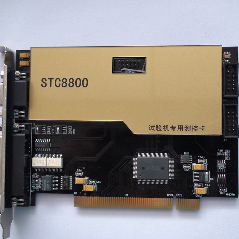
The self-made SmartTest controller and data acquisition and processing system of our company adopts the computer board and card design technology, which does not require the intermediate controller, makes full use of the hardware and software resources of the PC system, reduces the external communication port connection lines, realizes the direct control of the test system by the computer, and improves the control accuracy and control efficiency of the controller. The stability and reliability of the controller are greatly improved. The TTEST controller and data acquisition and processing system are verified by the field sampling test conducted by the national authoritative organizations according to the national Metrology technical specification of the People's Republic of China JJF1103-2003 « Universal Testing Machine Computer Data Acquisition System Evaluation » standard, and the technical indicators reach the advanced level of similar domestic controllers. It is praised by experts as the highest level of testing machine measurement and control system in China.
4 Professional electro-hydraulic servo testing machine general measurement and control software system
Software main technical features:
windowsXP/2000 operating system as the platform, all Chinese operation interface, set full digital electro-hydraulic servo closed-loop control, data processing, data analysis in one. Test force, deformation, displacement, stress and strain and other open/closed loop control function, control mode can be freely switched, the test data, loading rate, piston displacement and a variety of test curves by the computer screen real-time display, automatic data processing, and has a complete file operation function. The control system is supported by software system and easy to upgrade. Supports all kinds of commercial printers.
The main screen of the SmartTest software is shown in the figure after it is started.
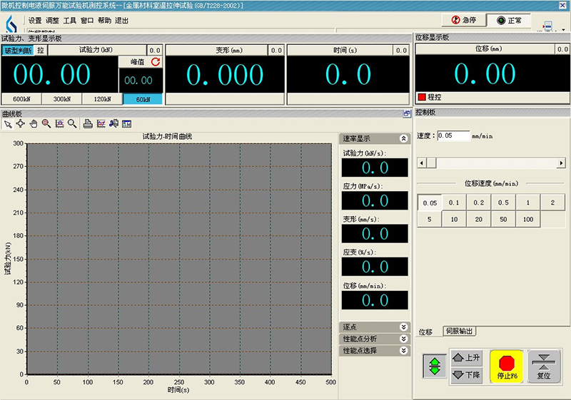
The main interface of the test operation is the control center of the program, which is responsible for the management of various functional Windows, and the test, data processing and program-controlled editing are all in this interface. It includes four parts: main menu, display module, function panel and control module.
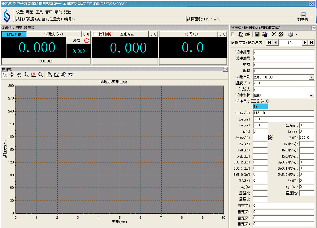
Data edition
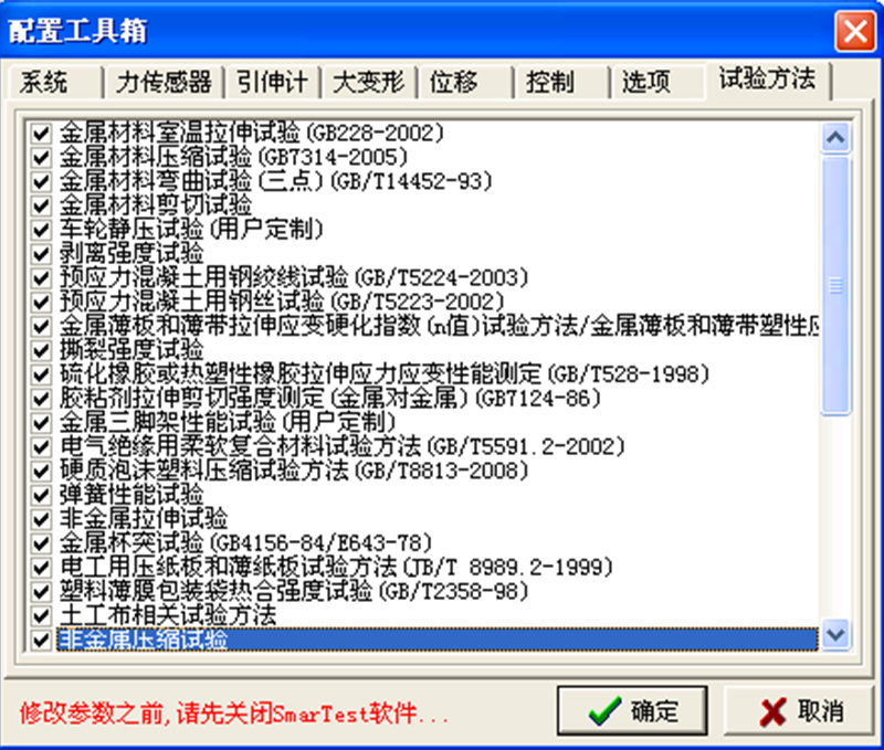
The control software has now integrated nearly 200 kinds of national standards or test methods, so many national standards can meet the needs of customers in various tests, test methods can be customized and updated at any time according to the needs of customers, which can bring great convenience to customers.
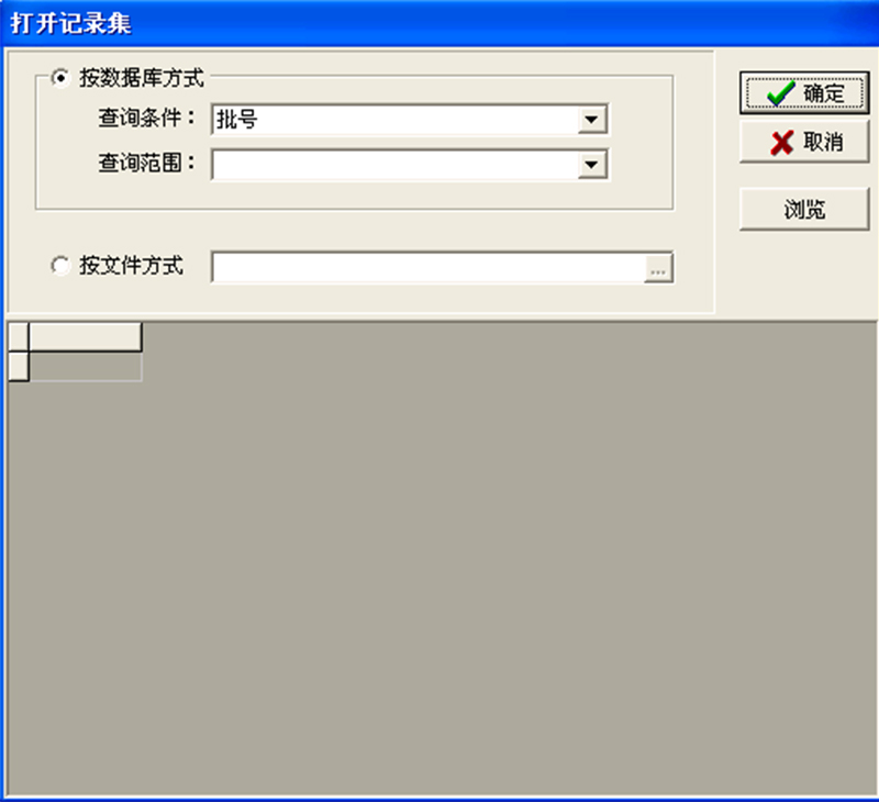
Data query window
Here you can query the historical test data in the database, just enter certain conditions, you can find the test data immediately.
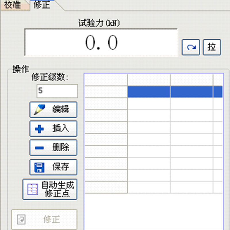
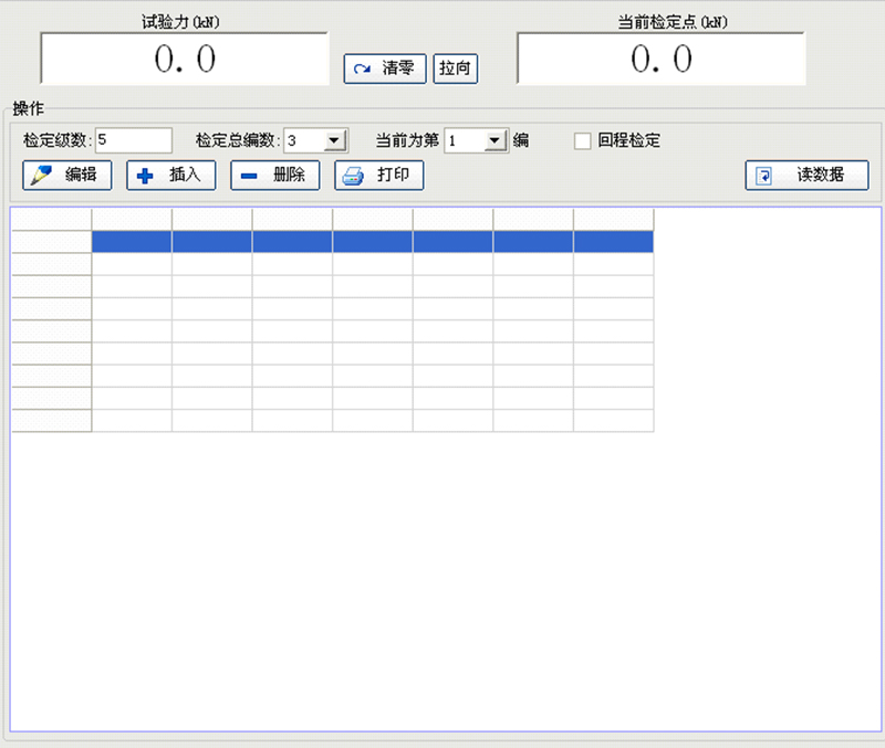
6) Calibration, correction and verification window
Force values and deformation can be calibrated, corrected, and verified.

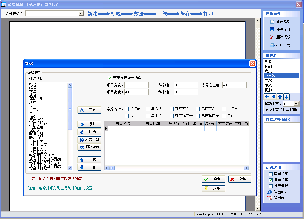
7) Batch data processing and batch report printing window
Here, a batch of similar specimens can be summarized and analyzed, the measurement and control data can be compared and the average value calculated, and the specimens can be summarized and printed in batches.
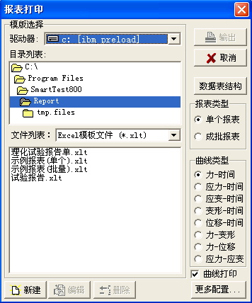
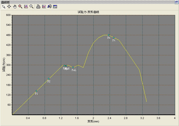
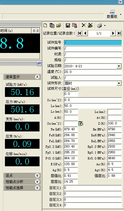
Curves and resulting data
During the test, six kinds of curves including displacement-time, force-time, force-displacement, stress-strain, force-deformation and deformation-time are drawn simultaneously according to the collected data, and can be switched arbitrarily between different curves
7.1 Electrical Parts
Electrical components:
The electrical part is composed of the control system and the display measuring system, and the load measuring system is composed of A high-precision pressure sensor, measuring amplifier, A/D converter, voltage regulator power supply, etc. All control parameters and measurement results can be displayed in real time on the large LCD screen. And has overload protection function.
The strong electric board and the measuring amplifier board are installed in the main machine, and are connected with the main machine, the measuring amplifier and the oil source through the connector to complete the transmission of power and signal. (See software manual for details)
High voltage board and system block diagram
System block diagram (see Figure 5)
7.2 Safety Device
7.2.1 When the piston moves to the limit position, the motor of the main oil source pump will be automatically stopped. When the system pressure is too high, the pressure relay inside the oil source will automatically disengage to achieve protection
7.2.2 When the load exceeds 2%-5% of the maximum test force, the test will be automatically stopped.
7.3 Testing machine Accessories
Attached with anchor chain tension test.
8. Hoisting and storage
The lifting equipment of the testing machine should be selected according to its volume and weight, and the lifting equipment should be carried out according to the center of gravity and lifting position marked on the packing box. It can be transported by rail and road. The testing machine should be placed in a dry and ventilated environment.
9. Installation and adjustment
9.1 Installation Conditions
The testing machine should be installed in a clean, dry, vibration-free and suitable temperature room. The position of the main engine, electric control cabinet and oil source of the testing machine should be determined according to the testing machine appearance drawing and foundation drawing. The upper plane of the foundation should be flat and levelled with a level. After the foundation is dry, install the testing machine.
9.2 Installing a Host
The testing machine and the oil source are respectively transported to the concrete base, and the distance and direction between the main engine and the oil source are determined according to the shape drawing and foundation drawing (see Figure 6) and the size of the tubing. Then a thin sheet is inserted between the bottom of the main engine and the foundation. Then use 0.05/1000 square level for alignment, place the square level on the outer surface of the cylinder, and find its verticality on the two sides perpendicular to each other. Its perpendicularity should not be greater than 0.2/1000. Or put the bar level on the work table, find its levelness, levelness should not be greater than 0.2/1000.
After the testing machine is found, the anchor nut is poured with water slurry, and the cushion iron under the machine base is firmly padded. And the gap under the base is filled with water slurry to maintain a good combination of the base and the cement foundation to prevent the testing machine from being horizontal due to vibration during use. After the anchor nut is poured, do not tighten the testing machine and start the main engine with anchor bolts before the cement is dry (the cement drying time is generally not less than 10 to 15 days). After the cement is dry, fix the testing machine on the foundation with anchor bolts. Check the installation accuracy of the testing machine to see if it is consistent with the alignment accuracy. If it does not match, correct it again.
9.3 Pipe Connection
The pipeline connection should be installed by professionals to avoid valve blockage and oil leakage due to misoperation.
9.4 Selection of hydraulic oil
Hydraulic oil should choose 46# anti-wear hydraulic oil.
9.5 Oil injection and discharge
Remove the clearance return pipe above the tank and inject oil into the tank through this oil filter. The amount of oil injected is measured by the level gauge on the side.
When discharging oil, open the drain nozzle at the bottom of the tank. The life of the oil is one year. It can be shortened and extended appropriately according to the climatic conditions of each place. If the oil is found to be deteriorated or dirty, new oil should be replaced.
9.6 Connecting Cables
According to the interconnection wiring diagram, the electric control cabinet, the main engine, the oil source, and the connector are connected, and the connection should be correct, secure, and reliable. (Power supply is three-phase 380, plus zero line. That is, three-phase five-wire system, machine shell grounding).
9.7 Mounting of specimens (see the attached figure)
Before the test, adjust the position of the fixed beam according to the length of the sample, then pull out the fixed pin in the above figure, put the sample in, and insert the fixed pin back to the original position. The other end is fixed in the same way
9.8 Operation Precautions
a) It is not allowed to use fast forward loading on the sample;
b) Motor phase sequence is not allowed to jump, (motor reverse transfer damage oil pump).
c) Determine the limit position before the test.
d) No action when turning on the power, please confirm: 1. Touch the limit. 2 Whether there is a fuse disconnect in the electrical control cabinet, as shown in the figure
e) After replacing electrical components or testing, please turn off the switch as shown in the figure
f) The system is controlled by microcomputer. Please do not install U disk or unknown software on the computer of the equipment when the equipment is running normally, so as to prevent virus damage to the system files. Please make a backup during normal use. Prevents the test software from being unavailable when the system is reinstalled.
10. Maintenance and maintenance
10.1 The components of the testing machine should be wiped frequently to prevent rust.
10.2 The hydraulic oil should be replaced regularly.
10.3 It is not allowed to disassemble the oil source and pipeline at will. If the oil leakage occurs and the seal is replaced, pay attention to cleaning the pipeline. This work should be carried out by professionals to avoid blocking the valve or scratch the cylinder piston, which will affect the normal use of the testing machine.
11. Common faults and troubleshooting methods
Oil seepage occurred in the tubing joint
Elimination method: First drop the piston back to the bottom of the cylinder, turn off the oil pump and power supply, and tighten the joint by hand. If oil is still leaking, replace the combined seal or O-ring.
12. System configuration list
1. Host system:
1.1. Single rod double action low friction cylinder
Imported seals are used to seal, seal reliably, use smoothly, and ensure the service life of the hydraulic cylinder.
1.2. Cylinder seat
1.3. Move the beam
1.4. Front and rear chuck seat
1.5. Main frame (steel plate welded structure)
1.6. Compression ball head accessories (data calibration)
2. Control the oil source
1. One electro-hydraulic servo integrated oil source (including electro-hydraulic servo valve)
2, a set of hydraulic clamping system (optional if the host is manually clamping, it does not include this)
3. Test a piece of ST8800 controller (inserted in a PC)
4, the electro-hydraulic servo testing machine general measurement and control software (backup CD) a set
5, a set of electrical system
6, a pressure sensor
7. An electronic extensometer
8. A set of photoelectric displacement sensor
9. A set of tees, cables and connectors related to the transformation
10, electronic manual (software CD-ROM) a set
11, a computer and color jet printer
other
6.1. Strong current system: one set
Desktop electrical console
6.2. Wire and cable, auxiliary devices, etc.
 Adhesive Stripping 90 Degree Stripping Testing Machine
 Wire Twisting And Winding Integrated Machine
 Adhesive 90-Degree Peel Strength Testing Machine
 NDS-10 Digital Display Metal Material Torsion Testing Machine
 WDW-1 Microcomputer Controlled Electronic Universal Testing Machine
 CPU-1020 Cup Convex Testing Machine