
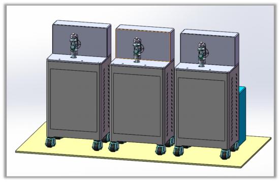
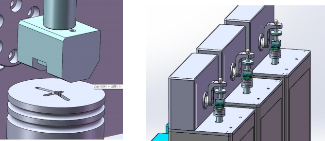
HH3 knee joint wear tester consists of three parts: test host, fixture, and electronic control part. It can simulate the wear, fatigue and peeling of knee implants and other damage processes, and can test 3 knee joints at the same time Implants.
1 .1 Features
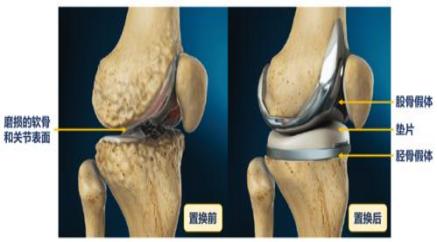
HH3 knee joint wear tester consists of three parts: test host, fixture, and electronic control part. It can simulate the wear, fatigue and peeling of knee implants and other damage processes, and can test 3 knee joints at the same time Implants. This testing machine automatically controls the test force, test time and speed, and measures the test force and torque in real time. It is applicable to the manufacture, use and research of knee joint prostheses and other related medical fields.
The spindle drive adopts imported AC servo motor and control system, which can realize stepless speed regulation and the required Calculate the constant torque/constant axial force output within the speed range; the test force is applied using a screw spring loading system. The test force is applied steadily and reliably, and the test force can be set by the operator on the computer interface; the spindle speed, The parameters such as the number of revolutions, test force, and test time are all controlled by a computer, which can collect test data in real time and plot them. The corresponding test curve can be made , and the test data or curve can be stored, retrieved and printed out at will.
Three- way servo motor driven loading system with different components for complete joint AP, rotation, flexion Abduction and other movements, the four-component force sensor module tests torque axial force, horizontal thrust and flexion respectively Torque during extension, three- way servo assembly equipped with high-precision rotary encoder, real-time angle measurement, and displacement and provide an effective data source for the host computer control.
Each motion mechanism is independently controlled and coordinated, with three stations and 15 axes to complete the grinding of joint components damage test.
1.2 Main Specifications
1. Instrument operation software with Chinese operation interface.
2. The instrument running software is ready to use, no special software is required.
3. Degrees of freedom: Each test station can realize flexion / extension, internal rotation / external rotation, forward / backward movement , three- dimensional motion control, and axial force loading, and each degree of freedom can be controlled. Both the sensor and the force are detected; free movement in the inward / outward direction and inward / outward direction is possible.
4. The nonlinearity of the sensor is not greater than 0.10% of the full scale, and the hysteresis is not greater than 0. 10%, repeatability is not more than 0.05% of full scale.
5. Displacement and displacement sensor range: axial displacement 100mm, flexion/extension 120, internal rotation/External rotation 20, anterior / posterior displacement 15mm, medial / lateral displacement 5mm, inversion/valgus.
6. Load capacity and force sensor range: axial load 3KN , internal / external torque 20Nm , Forward / backward load 1KN .
7. Force and displacement control accuracy: The error of force and displacement amplitude within one cycle shall not exceed the specified maximum The maximum phase error shall not exceed 3% of the full cycle. The instrument is tested in accordance with ISO 14243-1 and ISO 14243-3 in each controllable degree of freedom. Measured curves and deviation values of force and displacement sensors .
8. It has eight-channel analog input function and can be synchronized with external data.
9. Test frequency: 1Hz , accuracy 0.1Hz.
10. Control system: It should be equipped with a separate multi-station, multi-channel servo controller to achieve closed-loop automatic control of force and displacement.
11. The controller should be able to perform peak-to-valley value control compensation to ensure that the peak value required by the signal can be accurately reached when a cyclic waveform is used as a control instruction.
12. It should be able to implement programming testing of custom gait curves; be able to perform step- by-step manual control of each controllable degree of freedom; and be able to export raw data in Excel format.
13. During the test , the software should be able to reflect the force and displacement curves of each station in real time, and the control system. The system should be able to automatically adjust the sample's motion curve to match the target curve without manual intervention.
14. Real-time closed-loop control rate ≤ 6kHz , except for force and displacement control mode, the controller should be able to Implements the calculated variable control mode.
15. The digital sampling frequency should not be less than 100 kHz , and the sampling method should include: peak value, valley value, time time, maximum, minimum, average , cycle / logarithm, etc.
16. It has dual mode, channel feedback limit channel command working mode.
17. It has the function of self-checking the sensor excitation missing .
18. Temperature: The lubricating medium temperature can be maintained at (37 ℃) and there is a temperature control system.
19. Lubricating medium : The joint surface can be immersed in the lubricating medium, and the lubricating medium should be sealed without leakage; and equipped with a leakage monitoring device.
20. Test components: equipped with the necessary tooling for testing, loading workstations and loading for all movements The immersion workstation provides reference standard samples for equipment calibration and troubleshooting.
21. Emergency stop button: The equipment should be equipped with an emergency stop button.
22. Safety protection: The equipment should be equipped with a clear and transparent thermoplastic polycarbonate material protective cover; There is a safety interlock device. When the protective cover door is opened, the equipment should be able to automatically stop testing.
1.3 Working conditions
At room temperature Within the range of 10 ℃~ 35 ℃;
Relative humidity is not more than 80%;
Proper installation on a solid foundation;
In a clean environment without vibration, corrosive media and strong electromagnetic field interference;
The fluctuation range of the power supply voltage should not exceed the rated voltage 10% .
10% .
2. Structural composition
The test machine is divided into three workstations, which are the spindle drive system, the sample loading system, and the axial force The three workstations share the same spindle drive. Dynamic system and software control system.
2.1 Spindle drive system
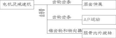
The axis motor uses Panasonic AC servo integrated speed control system and motor. The maximum motor power is 7.5 Kw, its power is divided into 3 output lines.
The first one: After the gear rack, electromagnetic clutch, and torque sensor, it becomes the rotating pendulum of the femur The electromagnetic clutch is responsible for controlling the power on and off, and the torque sensor is responsible for measuring the torque . Measure the torque during operation .
The second one: after passing through the toothed belt and gear rack , it becomes left and right reciprocating translation, driving the sample AP movement .
The third one: through the toothed belt , bevel gear and steering gear, it is converted into the rotational swing of the tibia, driving the sample to rotate inward and outward.
The transmission route is shown in the figure below.
2.2 Sample loading system
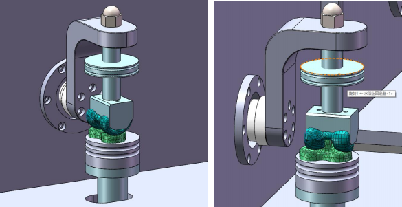
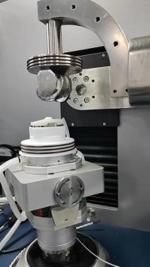
Specimen loading system simulates the freedom of motion under human conditions for the implant components of the knee joint It is installed and fixed. It consists of a mounting seat, a sliding seat, a nylon seat, a roller, a sliding sleeve, etc.
The specific implementation is as follows:
The installation of the knee joint wear tooling is relatively complicated. Please install it strictly according to the diagram. In addition, the corresponding channels are attached.
Please use the corresponding wire number when connecting the wires.
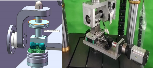
(The structure shown in the figure is only used to demonstrate the principle of movement, the actual object shall prevail)
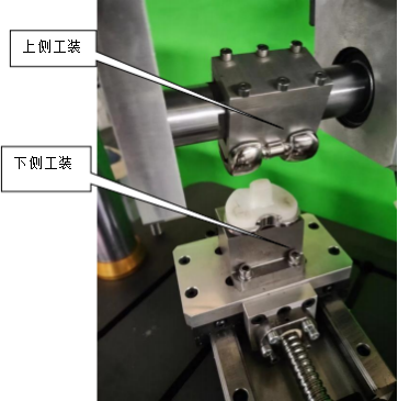
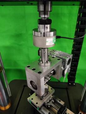
( The structure shown in the figure is only used to demonstrate the principle of movement, the actual object shall prevail)
You need to re -process the upper and lower tooling according to the sample to meet the test requirements. (Each product size Details vary)
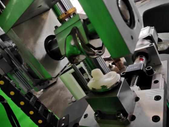
6. Channel selection and related adjustments
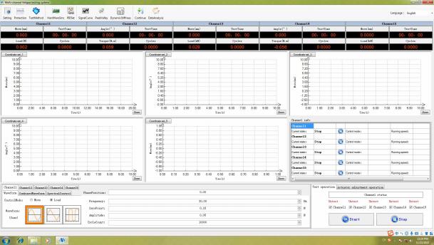
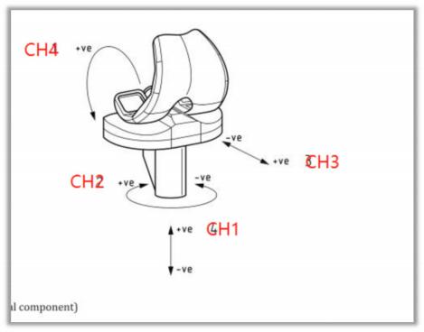
Combined with the above picture, check which channel is working by checking the channel. When executing ISO 14243.3 , select 1-4 aisle , Channel 5 is an expansion channel for subsequent upgrades. For other single-axis or dual-axis experiments, please select the corresponding channel.
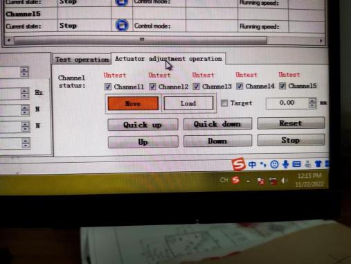
Quick up/up = fast loading/loading
Quick down/down = Quick down/down
7. Corresponding to ISO 14243.3 , it is necessary to import the control waveform, as shown in the figure:
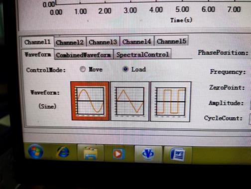
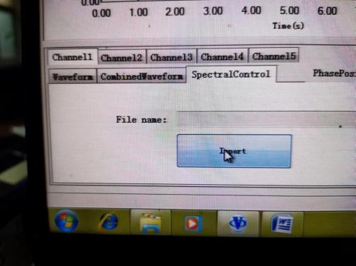
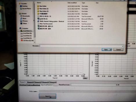
Select the factory preset waveform. If you need to set a new waveform or action, you can do so in this file. Modify and save under another name.
For detailed adjustments for each channel, please refer to the single-channel software manual.
8. About protection:
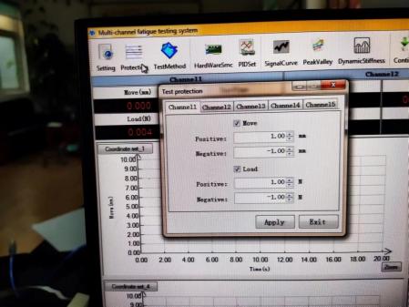
the experiment does not move or cannot be run after clicking Start, check whether there are any parameters set out of tolerance in the protection options.
2.3 Axial force loading system
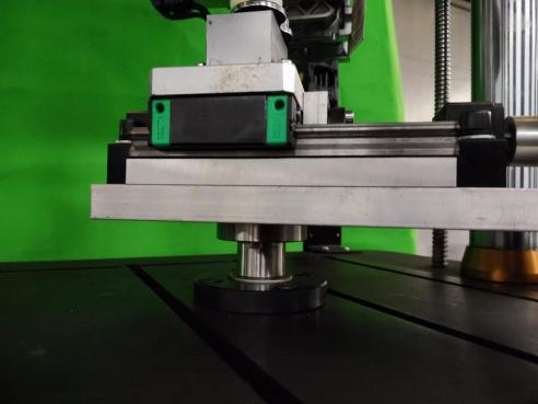
This machine adopts a spring loading structure. The loading mechanism is driven by a stepper motor, which is transmitted through a circular arc toothed belt, a synchronous pulley and a precision ball screw pair, and guided by a precision linear motion guide rail to drive the force application seat. The force -applying seat is fixed with a spring-loaded mechanism, which applies force to the sliding platform after the spring is compressed. The test force between the friction surfaces of the roller specimen is formed . By controlling the motor to drive the force seat to move forward and backward in space, That is, the application and magnitude of the test force can be controlled. A load sensor is installed on the plane of the force application seat. Collect force signals. Linear motion bearing guide ensures the application and stability of test force. Spring loading part Easy to load and unload.
When the test force starts to load, the sensor will input the preset pressure into the microcomputer control system and the preset pressure The microcomputer then controls the motor to reverse until the system pressure is balanced with the preset pressure.
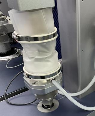
2.4 Load Soaking System
of an immersion liquid box, a heater, a temperature sensor, a peristaltic pump, a silicone tube, etc.
Customers can process positioning holes on the cylindrical end surface according to the actual size of the sample, and the clamping angle is adjustable. After adjusting the angle, lock the left positioning slider .
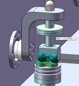
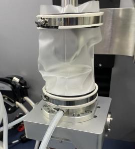
2.5 Software control system
The control system is installed on the control machine and connected to the test host through a communication cable. The software operating environment is WINDOWS XP. The control software is a graphical interactive operation interface, which is responsible for sending instructions to control the system start and stop, operating speed, loading force, immersion liquid temperature, and collecting system operation data such as axial force, torque, temperature, test time, etc. during the test. After calculation and processing, the test force-time, torque-time and other data curves are output in the form of charts.

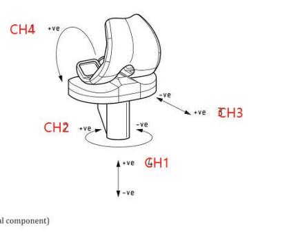
Combined with the above picture, check the channel to confirm which channel is working. When executing ISO 14243.3, select 1-4 channels, 5 the channel is an expansion channel for subsequent upgrades. For other single-axis or double-axis experiments, please select the corresponding channel.

Quick up/up = fast loading/loading
Quick down/down = fast uninstall/uninstall
7. Corresponding to ISO 14243.3 , it is necessary to import the control waveform, as shown in the figure:


Select the factory pre-made waveform. If you need to set a new waveform or action, you can modify it in this file. Save under another name.
For detailed adjustments for each channel, please refer to the single-channel software manual .
8. About protection:

the experiment does not move or cannot be run after clicking Start, check whether there are any parameters set out of tolerance in the protection options.
 Optical Cable Junction Box, Electrical Box, Optical Cable Box Sealing Performance Testing Machine
 NW-30 Bone Screw Torsion Testing Machine
 PDS1000 Fatigue Test System V3 For Orthopedics
 PDSN3030 Compression And Torsion Fatigue Testing Machine
 Dual Channel and Balance Bar Fatigue Testing Machine
 Tooth Material Reciprocating Friction Testing Machines