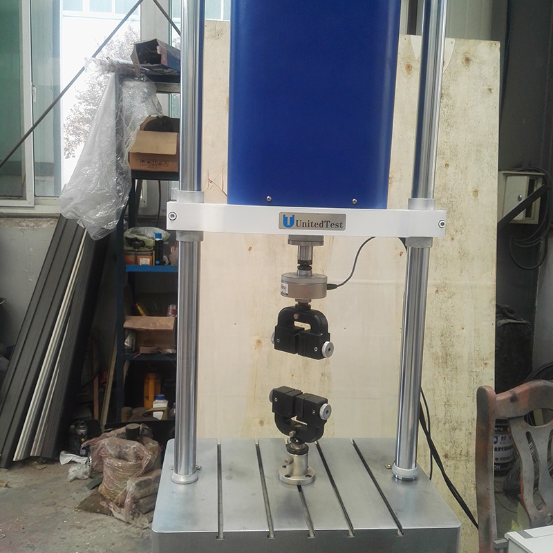
1. Series product introduction:
PDS series of microcomputer-controlled dynamic and static fatigue test system is one of the series of dynamic fatigue loading test system products developed by our company. This series of products has the characteristics of wide output force range, high control precision, easy to use and high reliability. This series of test system in the research and development process to absorb the international advanced electric servo cylinder drive technology, combined with the actual use of domestic users designed. Servo actuator, the selection of imported, loading frame and other key components for our company to design and manufacture, controller independent research and development, greatly improve the stability and reliability of the system, the overall performance of the testing machine with the international advanced product technology level.
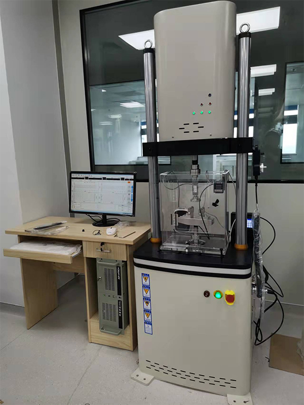
The test system can not only carry out dynamic high and low cycle fatigue test and program control fatigue test, but also carry out static constant rate, constant strain, constant stress control test and various conventional mechanical properties test, but also carry out fracture mechanics test. It can also test the fatigue life, crack growth, fracture toughness performance of materials or components in a broad range, safety evaluation of actual specimens, working condition simulation, etc., so it has the advantages that no other kind of testing machine can match, and is the most respected material testing equipment in the field of international fatigue mechanics research.
Because the system adopts adaptive gap-free electric servo actuator, the frequency response speed is fast, the noise is low, the energy saving and environmental protection, is very suitable for enterprises and research institutions to study and test small parts!
2. Advantages:
Linear motor technology without oil source ensures a clean test environment
The axial channel adopts Can bus control mode
High speed linear actuator
The unique driver bearing system ensures that the loading chain remains in alignment due to sample and fixture deflection or lateral forces
Suitable for dynamic and static testing of various materials and components
High dynamic performance, frequency up to 20 Hz
±10000N maximum dynamic axial load
Optical encoders are used for precise digital displacement control and deformation control of samples.
Single phase power drive, no additional hydraulic oil source, cooling water, pneumatic air
Digital controller based on advanced control methods in the industry
High stiffness, precisely aligned double column loading frame with driver located on beam
Dcell advanced load sensor technology for faster testing and reduced inertia
Flexible and versatile catwalk base suitable for assembling a variety of regular/irregular fixtures and samples
The instrument design is compact and compact - the rack covers less than 0.5 m²
3. Scheme description:
Main components of microcomputer servo dynamic and static fatigue test system:
1. Beam electric adjustment device,
2. Imported servo actuator cylinder, Japan Panasonic drive device;
3. Data acquisition control system: dynamic and static servo controller and Chinese software system
4. The United States imported dynamic special force sensor
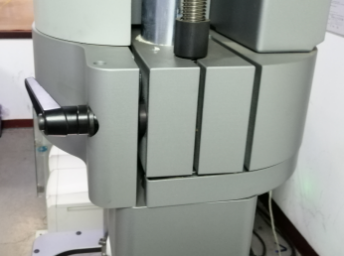
1.1 Unique spatial adjustment mechanism, the transmission parts are placed inside the beam, the double screw adjustment, the synchronous mechanism transmission, to ensure the smooth operation of the beam lifting, the adjustment speed can be adjusted, the speed can be slowed down when approaching the specimen, after the adjustment in place, the mechanical force strengthening mechanism is locked, convenient and labor saving.

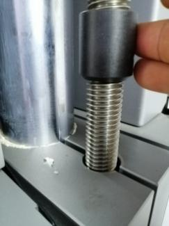
1.2 Servo actuating cylinder
The actuating cylinder is placed on the table plane.
Maximum test force: 10000N.
Actuator effective stroke: +/-50mm(total stroke 100mm);
The actuator comes with Japan (Tamuchuan) high-precision displacement sensor,
The actuator amplitude limit position is designed as buffer to avoid running out of control and causing damage;
The system adopts the anti-backlash device, the force value is automatically centered, the side force is reduced, the impact of the high frequency tensile test is reduced, and the test waveform is improved.
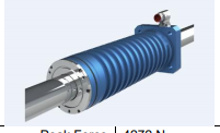
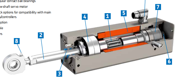
1.3 Sensors.
Load sensor (American World Bolt) : 10000N, overload capacity 120%. Placed in front of actuating piston with self-locking nut.
The sensor is calibrated before delivery.
1.4 Test accessories. (Customer optional fixture)
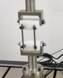

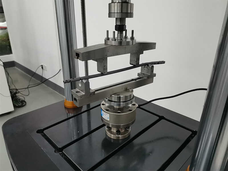
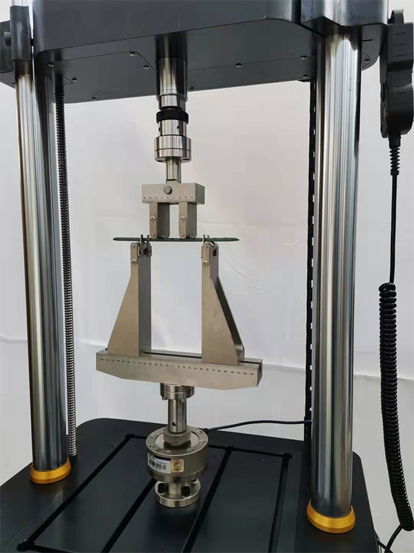
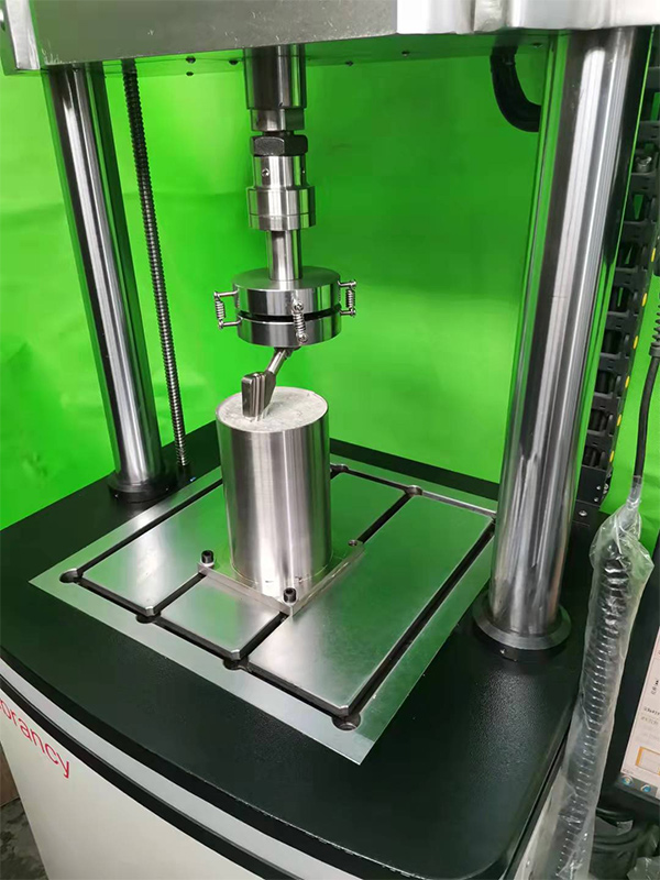
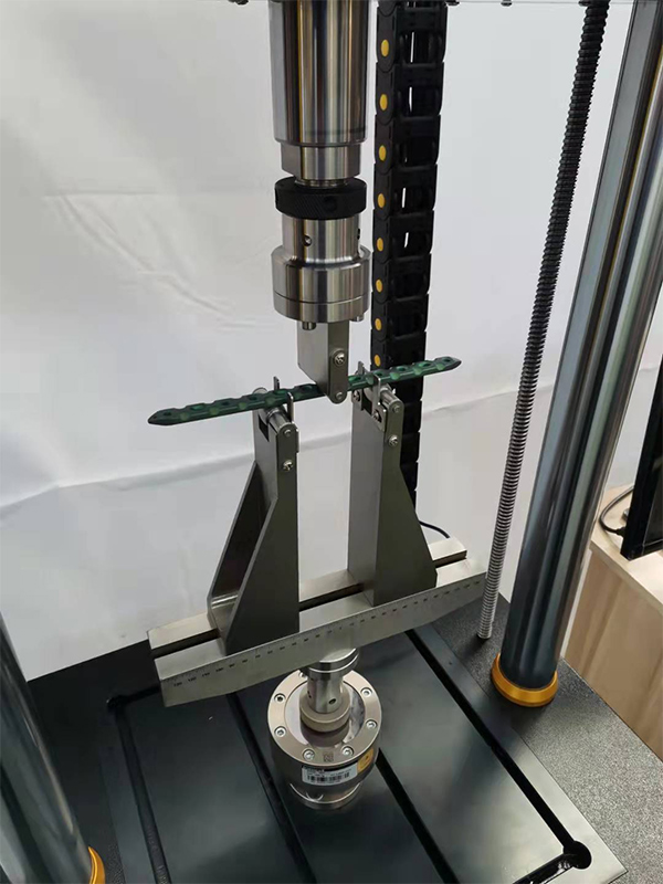
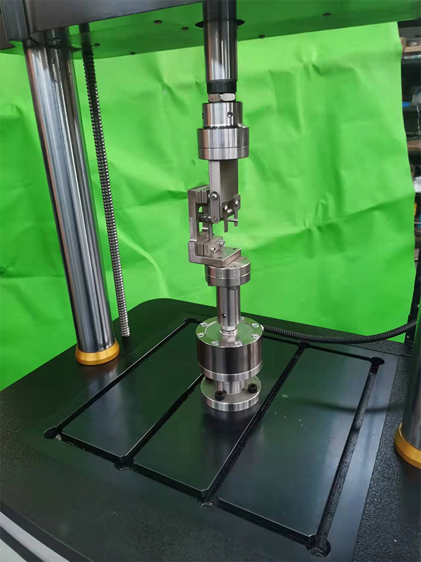
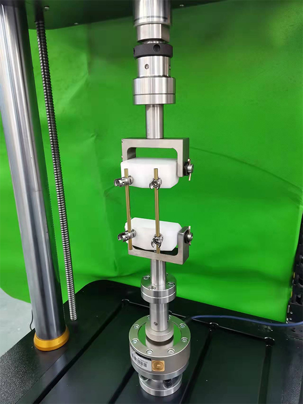
Can be designed according to user requirements.
Provide interface drawings.
NO.3 Data acquisition control system
Servo control part is composed of digital servo controller, industrial control computer and software and accessories.
Single channel full digital servo controller (including software system) as the system controller. The D8008 control system is used in this equipment as an independently developed advanced test system, which can fully ensure the advancement and reliability of the system.
3.1 Main Configuration of the Controller:
Scalable D8008 controller host station (up to 6 channels)
Signal conditioning unit with two sensors (force, displacement)
Signal generator unit
Computer workstation (mainstream brand computer, according to D8008 controller requirements) 1
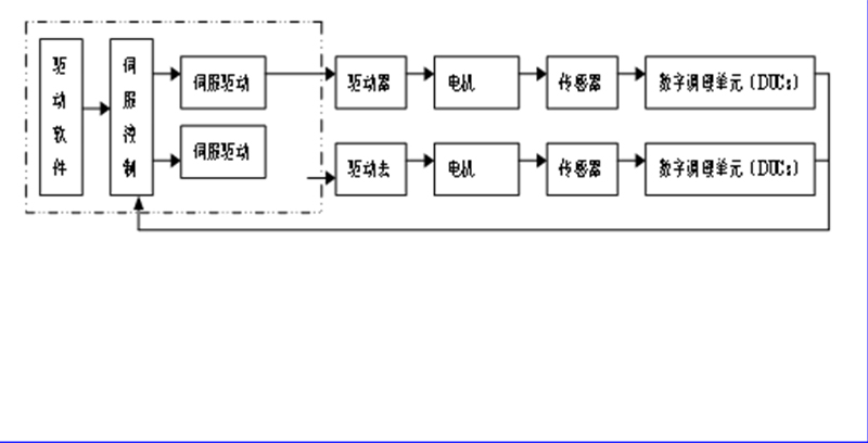
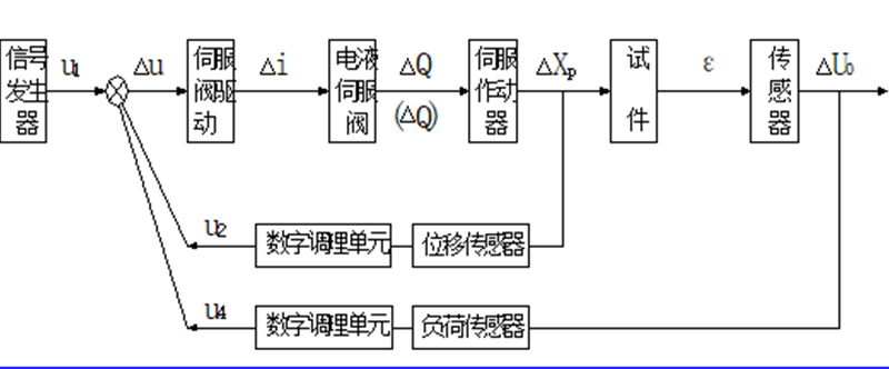
Figure 4 System control block diagram
3.2 Technical Specifications of the D8008.
Control unit: full digital PIDF control with arbitrary acquisition signal. Closed-loop control frequency :5kHz;
Frequency range: 0.01-1000Hz, frequency resolution: 0.001Hz;
Control waveform: sine wave, triangle wave, square wave, half sine wave, half triangle wave, half square wave, oblique wave, etc.
Control mode: Closed loop control of force and displacement, and smooth and undisturbed switching of any control mode can be realized.
The system has the functions of sensor calibration and zero clearing.
Through GPIB card and computer to achieve high-speed data acquisition, the maximum speed of data transmission 8M/s;
3.3 Functions of the controller
The D8008 controller is available with a variety of application software and packages. These kits meet a wide range of test needs. Moreover, the design of these software is consistent, and users can master the use of various suites in a very short time;
The calibration wizard system in the controller guides the user to carry out automatic calibration or manual calibration in more detail;
The controller adopts the most advanced technology in dynamic test control and data acquisition to improve quality and accuracy. Such as: adaptive control, automatic loop waveform setting and amplitude control, fully ensure the accuracy of the test and data;
The D8008 controller's fast and flexible software system meets a wide range of test requirements. The application software uses the least interface window to realize the display of all the required work. All data, graphs and figures can be exchanged with other Win programs, and users can create personalized reports.
The high resolution feedback sampling and signal adjustment technology of the controller improve the data quality of the digital servo controller to a new level. The whole process ungraded measurement technology ensures accurate and repeatable measurement data in the entire sensor range;
The D8008 controller is easy to expand, making it easy for users to invest in future upgrades. And with the growing needs of users to test, add new control channels to protect the user's investment.
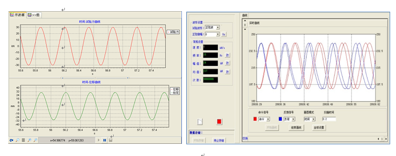
The test software provides a very easy way to set up and run simple tests. Automatic generation of test steps to achieve automatic control of the test process; Multiple compensation techniques can optimize control, even for challenging and complex tests.
The control channel of the D8008 controller has a variety of control modes, and can realize smooth and undisturbed switching of control modes. At the same time, it has the functions of non-fluctuation starting, automatic zeroing, saving and restoring PID Settings, saving and restoring test files, automatically collecting data, protecting samples during the test, etc.
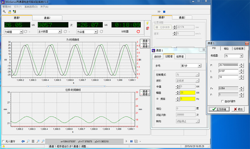
3.4 Software System:
3.5 Computers and Printers.
21" LCD display.
Pentium cpu 2.2GHz, 8GB memory.
1T + hard disk, DVD-RW,101 keyboard.
Windows 10 operating system.
The HP printer.
4. Main technical indicators
Maximum test force: ±10000N;
Test force accuracy: within the range of 2%-100%FS, each point is less than ±1.0%;
Fluctuation of dynamic indication of test force: 0.5%FS;
Maximum displacement of actuator: ±50mm; Indication accuracy ±0.5%FS;
Main test waveform: sine wave, square wave, triangle wave, oblique wave, etc.
Test frequency: 0.01-20Hz;
Test space: 440*500*650
The amplitude-frequency characteristic curve of the system is as follows:
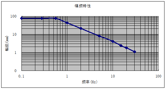
Under sine wave conditions: Reference
Test accessories: Compression accessories: one set; In addition, interface drawings are provided to facilitate users to prepare their own tooling.
Others: as described above.
5. Confidentiality of technical information and data:
4.1 This technical scheme belongs to the technical data of our company, and the user shall assume the obligation of confidentiality of the technical information and data provided by us. Regardless of whether this scheme is adopted or not, this clause shall be valid for a long time.
4.2 We shall also be obliged to keep confidential the technical information and materials provided by users.
6. Other:
1. Project Management:
The project manager is responsible for coordinating the planning, production and delivery of the project.
2. Project design review:
If the user and project manager deem it necessary
Expected review time: 1 day
3. System design:
The company designs all mechanical, electronic, hydraulic and software.
4. System inspection:
The company inspects, operates and calibrates the system prior to shipment.
5. Documents:
System operation manual.
System software user manual.
System operation guide and related information.
System drawings for use, spare parts list, etc.
Certificate, packing list.
6. Pre-acceptance and inspection
Before shipment, the company will conduct a final inspection of the system:
Count all user purchases.
Verify all mechanical, hydraulic, electronic and software functions.
Verify correct no-load performance of the system.
Before delivery, if the project manager or customer deems it necessary, the user will be invited to pre-acceptance and inspection, and the user will provide samples. Any additional items included in the pre-acceptance shall be approved by both the user and the project Manager during the project review.
7. Unpack and check
If necessary, a service engineer or representative will perform on-site supervision as system components are unboxed and placed in place.
8. Installation
Our service engineers will install and check the functions of the system at the user site and provide training to the user. User provides sample.
9, user site acceptance and inspection.
The company will work with users to carry out acceptance tests on the equipment at the site.
10. Warranty.
Free maintenance is provided for 12 months after installation. All parts provided are serviced free of charge during the warranty period. Consumables are not covered by warranty.
11. Spare parts and tools: Provide related tools; A suit of
7. Quotation: See the quotation document for details
8. Delivery date.

 English
 Español
 Português
 русский
 français
 日本語
日本語
 Deutsch
 Italiano
 Nederlands
 ไทย
ไทย
 Polski
 한국어
한국어
 Svenska
 magyar
 Malay
Malay
 বাংলা
বাংলা
 Dansk
Dansk
 Suomi
Suomi
 Pilipino
 Gaeilge
 عربى
عربى
 norsk
norsk
 اردو
اردو
 čeština
 Ελληνικά
 Українська
 فارسی
فارسی
 தமிழ்
தமிழ்
 తెలుగు
 नेपाली
 Burmese
 български
 ລາວ
ລາວ
 Latine
 Қазақ
Қазақ
 Euskal
 Azərbaycan
 slovenský
 Македонски
 Lietuvos
 Eesti Keel
 Română
 Slovenski
 मराठी
मराठी
 Српски
 עִברִית
 icelandic
 Беларус
 Монгол хэл
 Javanese


